Electrical Wiring Diagram Of Air Conditioner
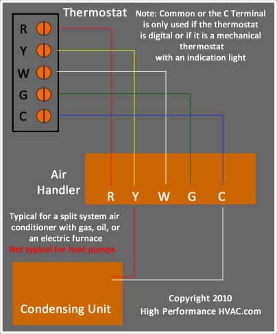
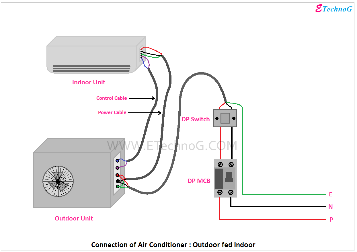
G terminal to the green wire.

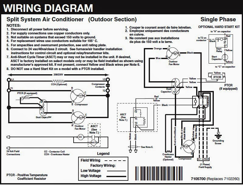
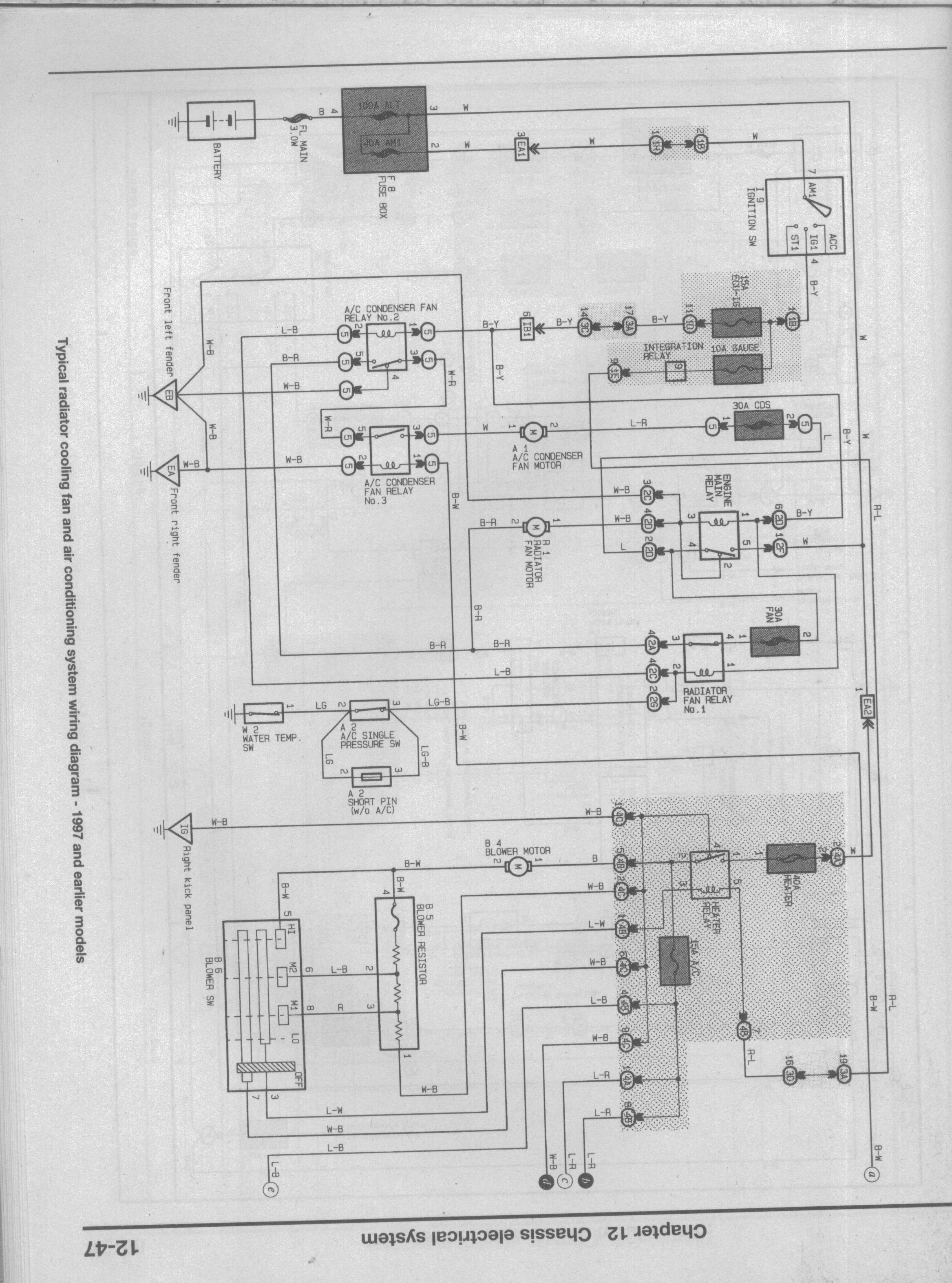
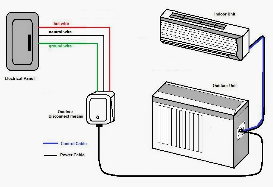
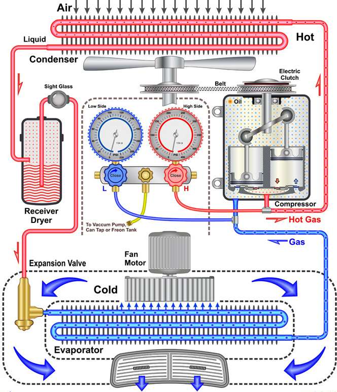
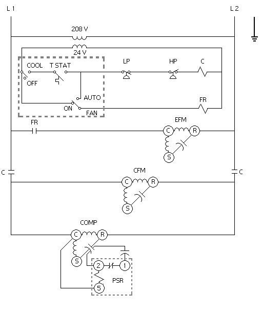
Electrical wiring diagram of air conditioner. In article electrical rules and calculations for air conditioning systems part one which was the first article in our new course hvac 2. Electrical wiring diagrams for air conditioning systems a part two. A wiring diagram is a simplified traditional pictorial depiction of an electric circuit. Y terminal to the yellow wire.
W terminal to the white wire. Red wire for air conditioner control power hot. Introduction for air conditioning systems types introduction. Electrical rules and calculations for air conditioning systems i explained the following points.
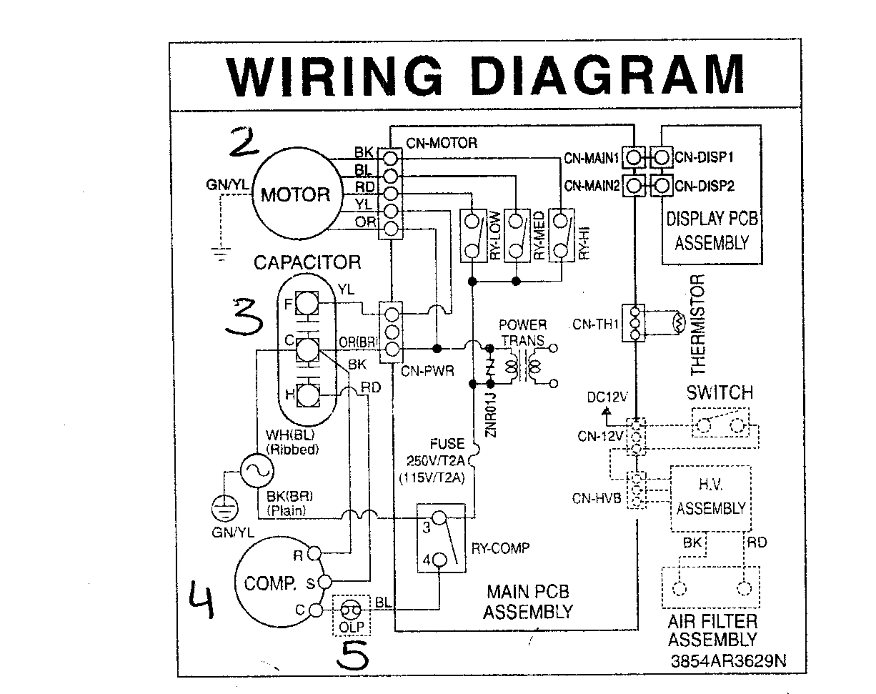
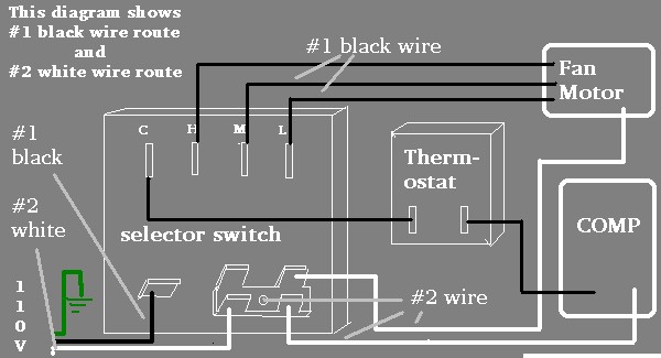
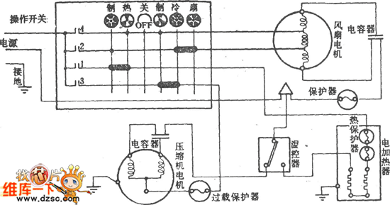
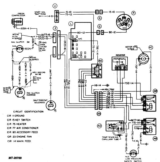
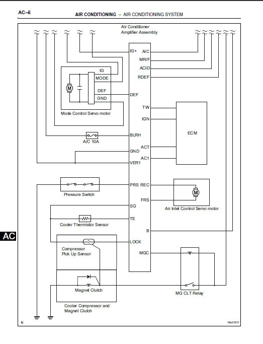
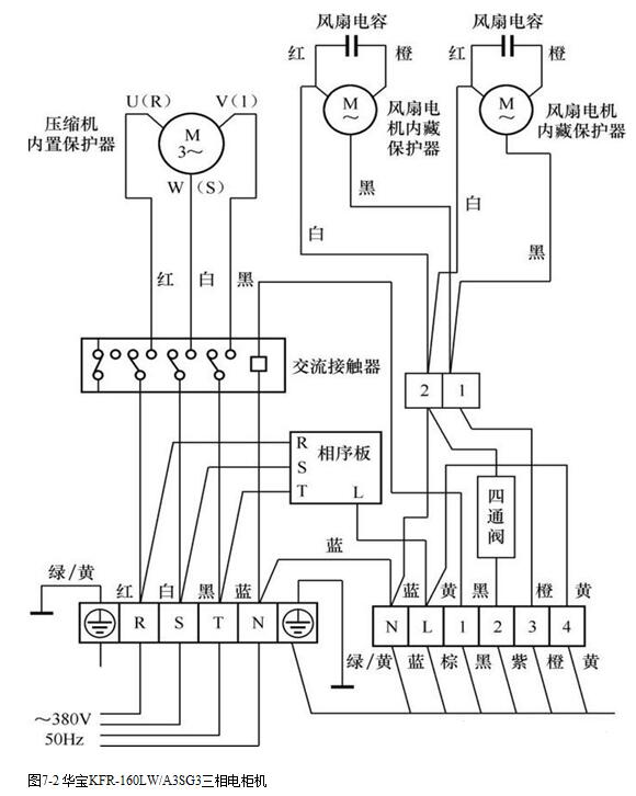
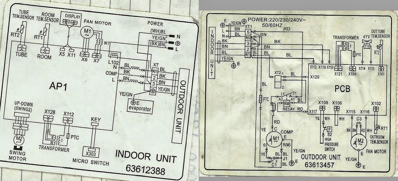
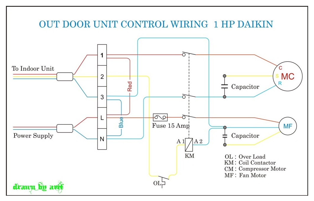
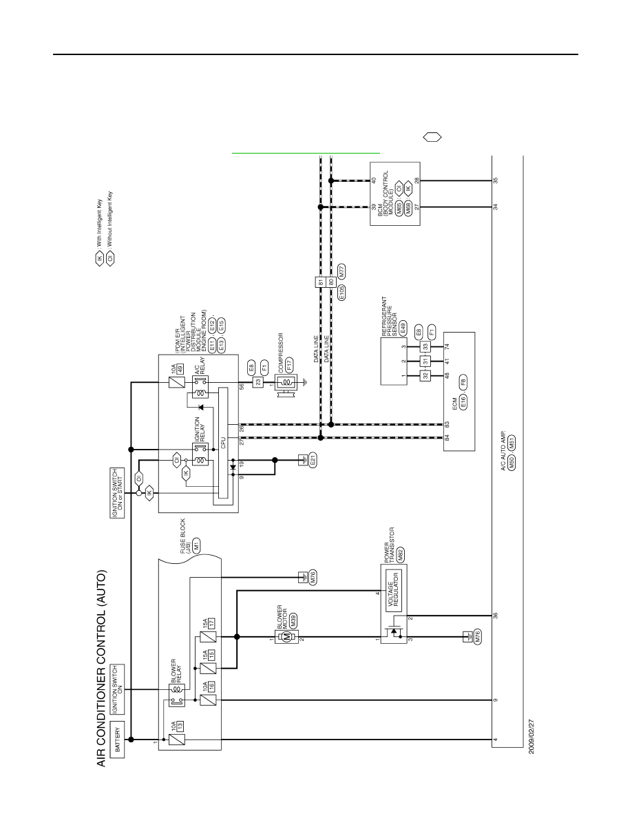
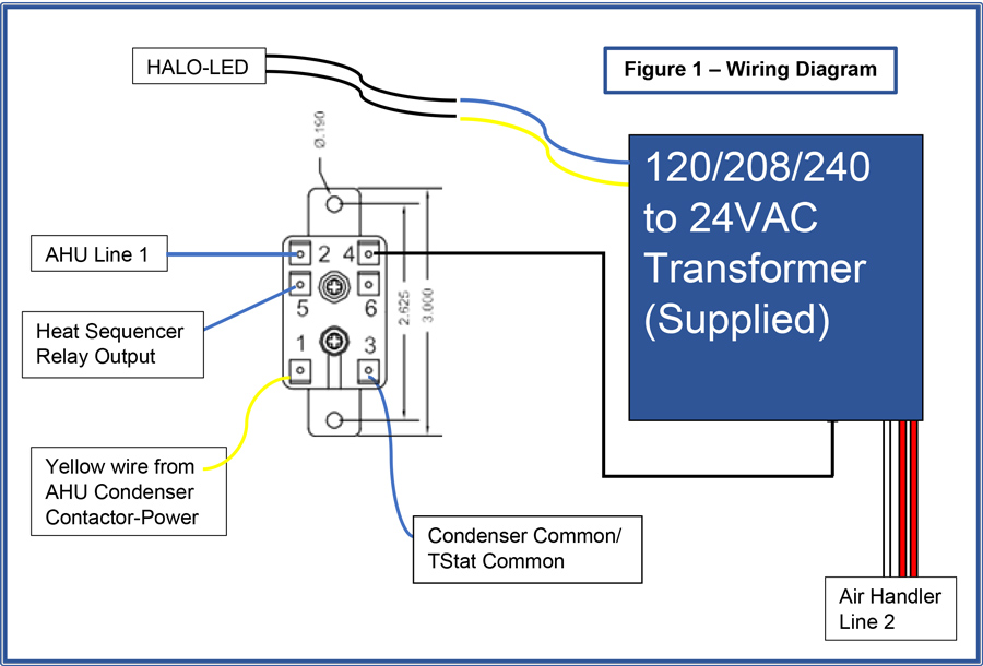
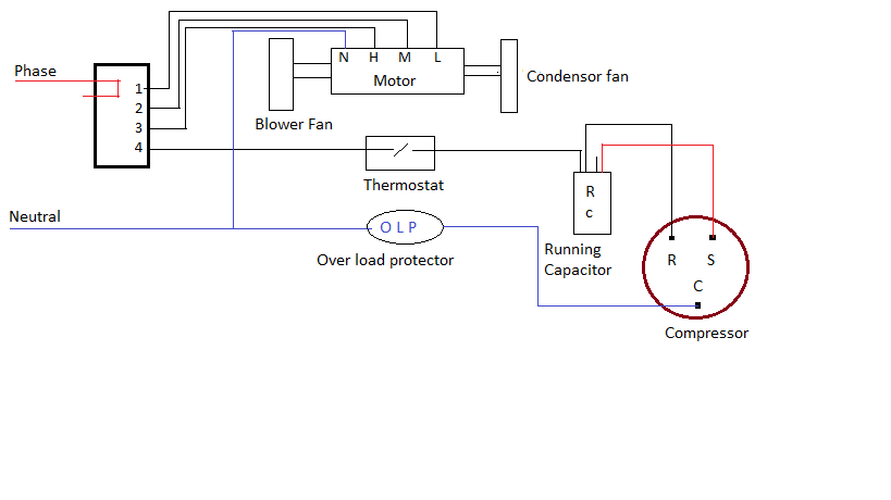
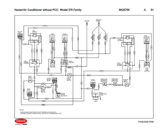
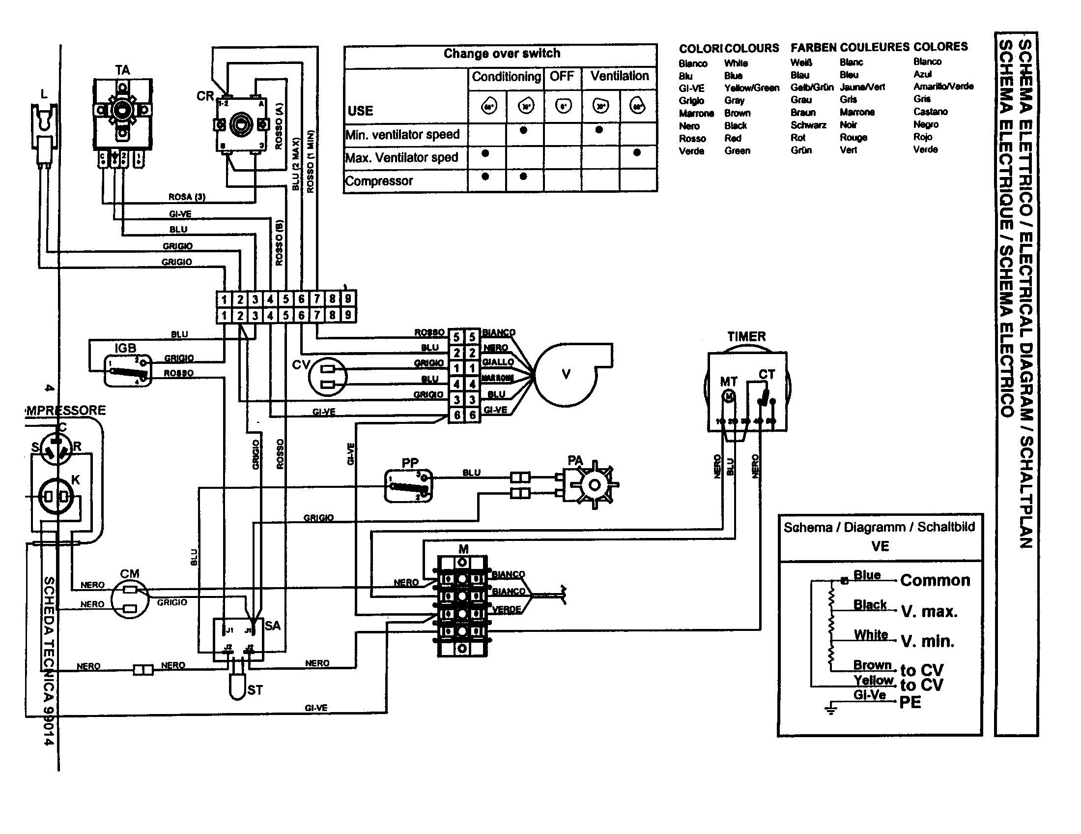
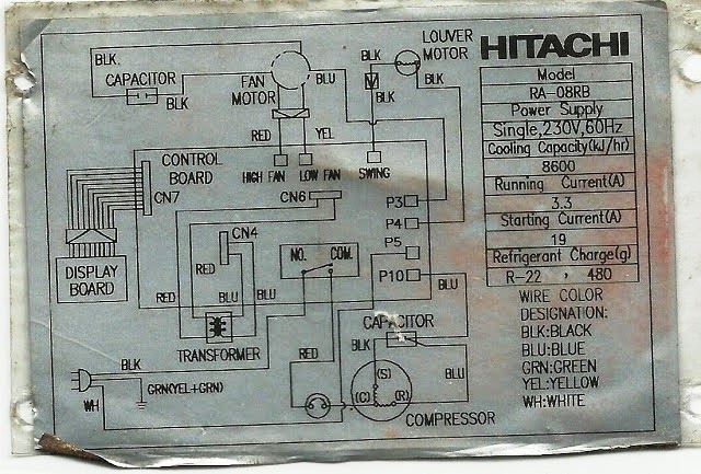
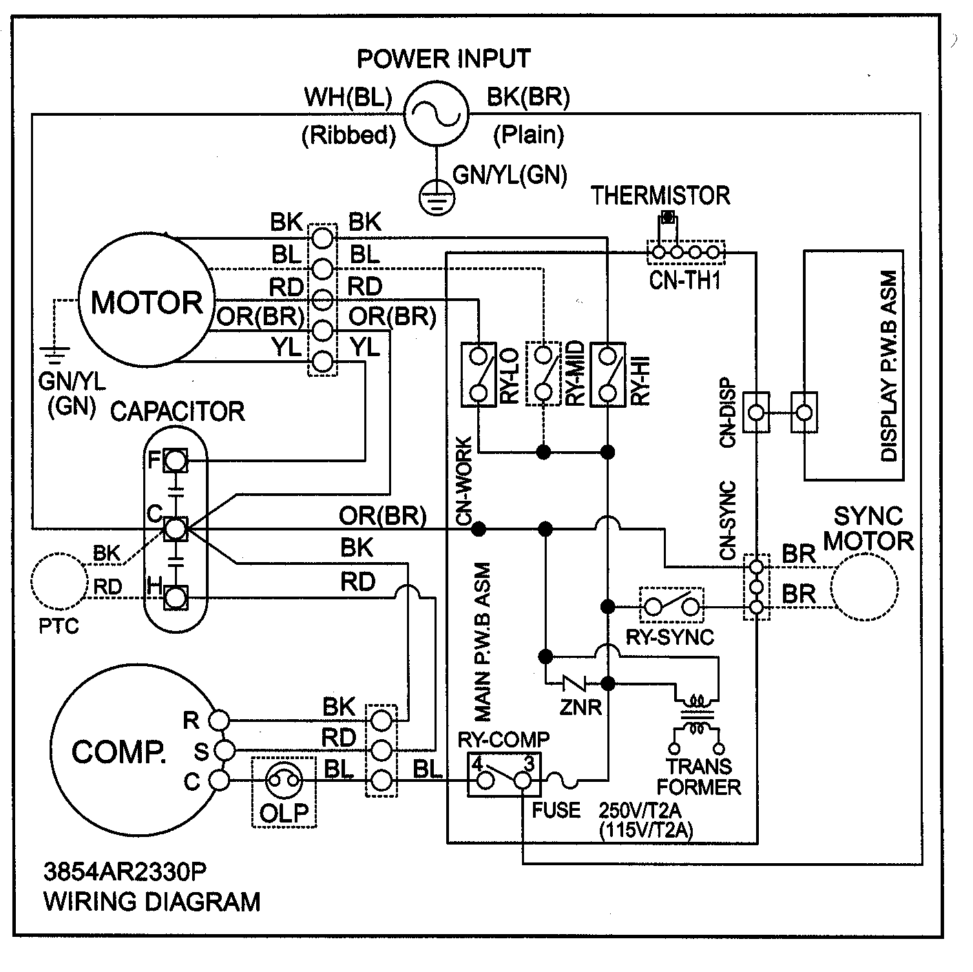
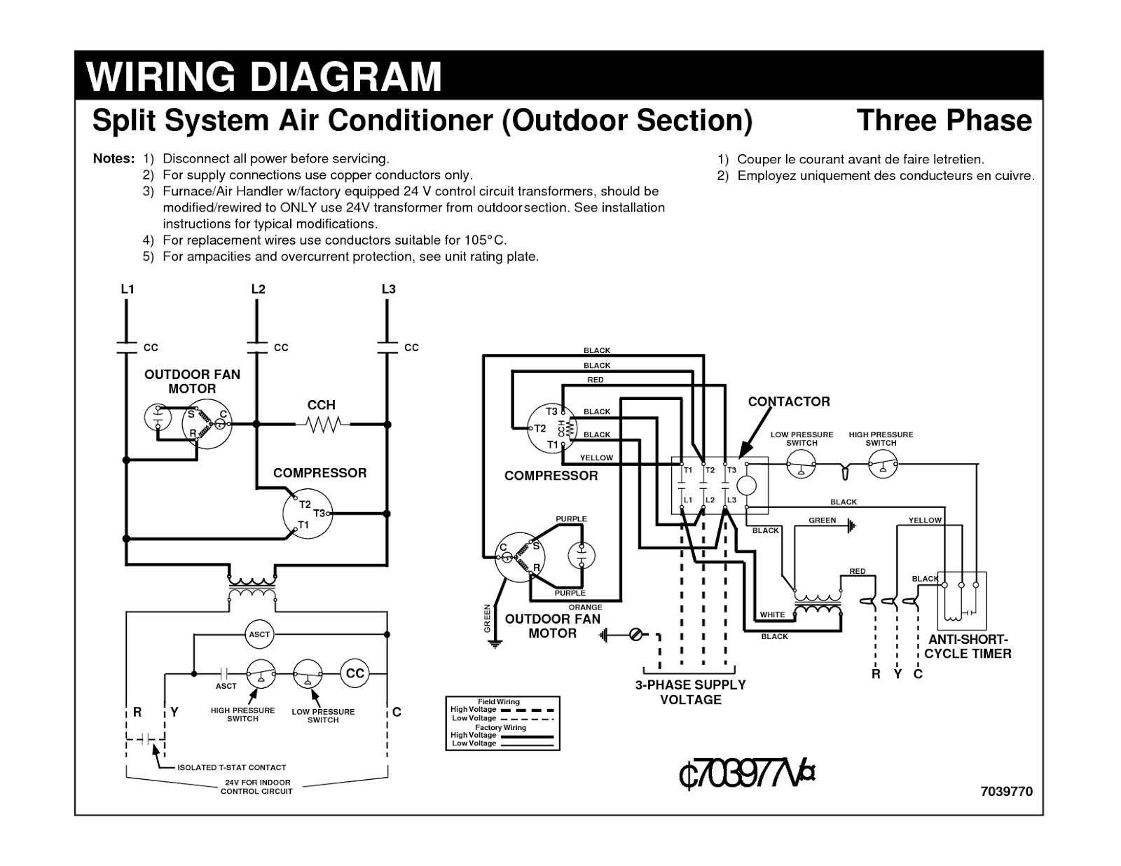
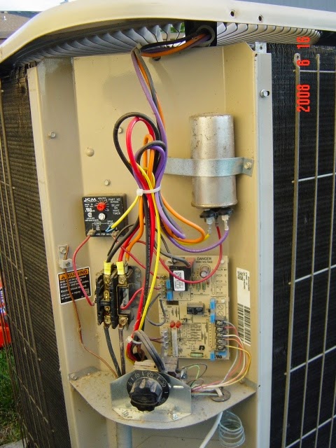
Usually the electrical wiring diagram of any hvac equipment can be acquired from the manufacturer of this equipment who provides the electrical wiring diagram in the users manual see fig1 or sometimes on the equipment itself see fig2. Window air conditioning unit electrical wiring diagrams touch and remote control type 14 the power flow inside a typical window air conditioning unit in the cooling mode when you turn the selector switch to cool mode the power that came in from the cord that connected to the selector via hot wire goes to the fan so the fan operates. It shows the parts of the circuit as streamlined shapes and the power and also signal connections in between the gadgets. How to wire an air conditioner for control 5 wires.
C terminal to the blue wire. November 3 2018 by larry a. It shows the components of the circuit as simplified shapes and the power and signal connections between the devices. Wellborn collection of central air conditioner wiring diagram.
A wiring diagram is a streamlined standard photographic depiction of an electric circuit. Collection of air conditioner wiring diagram pdf.

